DAPL Operating System | Processing Command
Module SENSORM :: DIVIDER
Convert measurements from a voltage divider network to determine resistance.
Syntax
DIVIDER( VIN, VS, RLOAD, [RCOEFF, LTMP,] [GAIN,] ROUT )
Parameters
- VIN
- Input measurements of divider voltage
- FLOAT PIPE
- VS
- Nominal or measured excitation voltage driving divider network
- FLOAT CONSTANT | FLOAT PIPE
- RLOAD
- Nominal or calibrated load resistance, ohms at 0 degrees C
- FLOAT CONSTANT
- RCOEFF
- Temperature coefficient of resistance for load resistor
- FLOAT CONSTANT
- LTMP
- Input pipe with load temperature measurements, degrees C
- FLOAT PIPE
- GAIN
- Gain used to measure input signal
VIN - FLOAT CONSTANT
- ROUT
- Output resistance measurements, in ohms
- FLOAT PIPE
Description
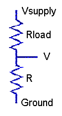
The DIVIDER command converts voltage readings
to measure an unknown resistance. The unknown device to be
measured is placed in a voltage divider network with an
accurately-known loading resistor. The divider network is driven
by an accurately-regulated voltage source, and the voltages
VIN are observed at the junction between the
unknown element and load resistor. The results, in ohms, are
returned through the ROUT pipe, one result per
divider measurement input value.
The input divider voltage measurements are received through
the VIN pipe. These measurements have units of
volts. By default, this command assumes that the voltage
measurement are obtained using an amplifier gain of 1.0, but if
you use a higher gain, specify it as the GAIN
parameter.
If the supply voltage is very well regulated, you can
measure it once and specify the value as a constant VS
parameter. If you use the regulated voltage from the
data acquisition processor for this excitation, you could
specify 5.0 volts and omit the calibration measurement. If the
excitation is subject to small but potentially relevant
variations, make simultaneous voltage measurements of the supply
voltage, in units of volts, and provide this second input stream
to the DIVIDER command through the VS
pipe, one supply voltage measurement per divider voltage
reading.
Specify the loading resistor value RLOAD
parameter in units of ohms. Sometimes a nominal resistor value
is close enough, but for better results enter an accurately-
measured value.
Most of the time, variations in operating temperature are
insignificant, and the load resistance can be presumed constant.
For these cases, omit the RCOEFF and
LTMP parameters. However, if significant temperature
variations are anticipated, the DIVIDER command
can adjust the effective load resistance to compensate for
temperature-dependent changes. Set the RCOEFF
parameter to the temperature coefficient of load resistance in
ohms per degree Centigrade. Adjust the RLOAD
parameter if necessary so that it reports the correct loading
resistance at 0 degrees Centigrade. Measure the load
resistance temperature in units of degrees Centigrade and
send these measurements to the DIVIDER command
through the LTMP pipe, one temperature
reading per divider measurement.
For processing each input value, the difference between
the known excitation voltage source and the measured divider
junction appears across the known loading resistor, hence the
divider current can be computed. This known divider current
passes through the unknown element to produce the measured
voltage, so its resistance can be computed, producing the
results placed into the ROUT pipe.
Examples
DIVIDER(IP2, 5.000, 10000.0, ROUT)
Read the voltage at the junction between a load resistance
of exactly 10K ohms and an unknown resistive sensor when a 5.000
volt excitation voltage is applied across the divider network.
The voltages across the resistive sensor element are measured
with gain 1 and received from input sample channel pipe
IPipe 2. The computed resistance values are
reported in pipe ROUT.
DIVIDER(IP2, 4.968, 10008.0, 0.42, PAmb, 4.0, ROUT)
This example is the same as the previous configuration,
except calibrated for maximum measurement accuracy. The
pre-measured supply voltage level is 4.958 ohms is specified
as a constant. The measured load resistor value is 10008
ohms. The nominal load resistance is observed to increase by 42
ohms over a 100 degree temperature swing, so a temperature
coefficient 0.42 ohms per degrees C is specified. The
measurements of divider voltage are captured using an amplifier
gain of 4.0. The operating temperature is separately measured
and provided in the PAmb pipe. The computations use
a temperature-adjusted value of load resistance for each
conversion.
See also:
BRIDGE