First Realistic Off-Vehicle Testing of Transmission Components
View more Control information.
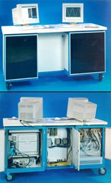
What its developer believes is a breakthrough in providing realistic Laboratory testing of automatic transmission components such as torque converter clutches has been delivered to a major automotive manufacturer. Testing automatic transmission components is challenging because it is difficult and costly to devise a method for instrumenting critical components such as torque converters in an operating transmission. On-vehicle testing can determine the life of the components after the transmission is taken apart, but provides little or no information on critical operating parameters such as the torques, hydraulic pressures and temperatures that they see. The new test rig with controls developed by FCS COM, Inc. [later Moog FCS], Ann Arbor, Michigan, uses two dynamometers, one to drive the component under test and the other simulating the real world load conditions. The test specimen is instrumented with strain gauges and thermocouples which when connected to a telemetry collar provide real-time information from the rotating part. The result is that, for the first time, engineers can control the slip in torque converter clutches, evaluate different component designs and immediately see how their performance varies. A key factor in making this system affordable is its use of a unique data acquisition processor, from Microstar Laboratories, Bellevue, Washington, that runs mission critical real-time operations independent from the non-real-time graphical user interface. This approach increases reliability and, with FCS COM's Finite State Machine (FSM) software, saves the $20,000 to $30,000 that would otherwise be required for a programmable logic controller (PLC) system to provide safety monitoring and machine control.
Two-Dynamometer System Slip-Tests Transmission Components
COM's engineering team configured the DAP to provide a software control loop for the test rig. The Windows interface provides the basic dynamic commands to the rig. Each of these commands goes through a finite state machine developed in DAPL by COM engineers. The DAP communicates with Windows through a watchdog interface. Should Windows fail to respond to the watchdog timer, the finite state machine takes over and brings the test rig to a safe stop.
“One of the keys to the success of this project was our ability to add a real-time processor to a PC in order to keep the mission-critical functions in a separate processor.”
John Ritter, VP System Development, FCS-COM
In current practice there are two basic methods of testing critical automatic transmission components such as torque converters, both of which leave something to be desired. The first method is simply running full vehicle tests on either a dynamometer or proving ground. This approach provides valuable information in evaluating the durability of the overall design. Yet, it is a relatively poor tool for component-level design because of its expense, lead-time and the fact that it would be very costly to provide the instrumentation needed to measure operating parameters on individual components. The other approach is to test transmission components in a laboratory, normally by driving one side of the component while the other is fixed to the machine. The dynamometer typically is cycled through a series of loads. The problem with this approach is there is no way to correlate the loads seen by the component with a real world vehicle. With one side spinning and the other fixed, what the component sees is different from the situation in a real transmission. So while general information can be obtained, such as the ability of different friction materials to withstand certain operating temperatures, the ability of this type of device to evaluate the relative performance of alternate design concepts is limited.
Design of constant slip test rig
A major automobile manufacturer asked FCS COM, Inc. to develop a constant slip test system that would accurately simulate real world transmission conditions. The basic idea was to use two dynamometers, the first simulating the automobile driving the transmission, and the second simulating the resistance of the driveline, tires and road. The main idea of recreating the conditions seen by the component was to make it possible to instrument it so that its operating conditions could be clearly measured under various scenarios. FCS COM's design to accomplish this involved instrumenting components attached to both dynamometers with sensors and using telemetry collars to transmit these signals to a data acquisition device. Sensors used in the test rig measure rpm, torque, strain, temperature, pressure and other parameters. This makes it possible to perform measurements that have never been accomplished before, such as measuring the amount of torque that causes a clutch to break away and begin slipping under a real-world control profile. This answers a major need of the automobile OEM, to be able to change their design, such as by using a new friction material or a different plate geometry, and immediately measure the impact on the operation of the torque converter.
While there were several challenging aspects to the design of the test rig, controlling the two dynamometers was perhaps the most critical aspect. The inputs applied to the dynamometer are based on measurements taken in road tests. Certain measurements can be easily taken on an automatic transmission such as the rpm, and torque going into and coming out of the transmission. It's also possible to measure the pressure and temperature of the hydraulic fluid used to operate the torque converter. The torque and rpm applied to the input of the transmission are used to determine the control signal for the driving dynamometer. Determining the signal for the second dynamometer is more complicated. A mathematical model developed by the automotive OEM is used to transform the road testing data to determine the operating signal for the second dynamometer that will duplicate these parameters. The automobile OEM wanted an easy-to-use graphical user interface to operate the test rig but, aware that Windows is not a real-time operating system, needed some other method to provide safety and limit checking on the rig to, most importantly, ensure the safety of personnel and, secondly, avoid damage to equipment and components.
An alternative to PLC control
The traditional approach would have been to use a PLC, a digital controller used for applications such as on/off control, timing, logic, counting and sequencing, in between the graphical interface and the machine. PLCs are frequently used to control complicated machinery because they possess the stability and deterministic real-time capabilities needed to ensure that machines remain under control and follow prescribed shutdown procedures in case of a fault. Operating systems like Windows NT use up a lot of cycles on the PC platform and when they take control of the CPU they hold onto it for a long time in machine control terms. A failure of the operating system could leave the machine in an unknown and possibly dangerous state. In measuring or controlling a real-time process, computing power has to be available when it is needed. But incorporating both a PLC and a personal computer would have driven up the cost of the machine.
FCS COM engineers searched for an alternative that would help to keep the cost of the machine affordable. They had previously used data acquisition processors (DAPs) from Microstar Laboratories in several other projects such as a smart press used to develop prototype parts and processes for automotive components and dynamometer control systems for full transmission testing. The unique capability offered by DAPs is an onboard microprocessor that runs a multitasking, real-time operating system optimized for high-performance real-time data acquisition and control applications. DAPL, the onboard operating system used in DAPs, simplifies communications by providing over 100 easy to use commands optimized for data acquisition and machine control. This intelligence on the DAP board is designed to extend the power of the Windows user interface by executing all processor intensive routines in real time and performing data reduction so that the software on the PC can handle more demanding applications than usual. Onboard intelligence tipped the balance in favor of choosing a DAP for this project.
Finite state machine provides real-time control
FCS COM's engineering team configured the DAP to provide a software control loop for the test rig. The Windows interface provides the basic dynamic commands to the rig. Each of these commands goes through a finite state machine developed in DAPL by FCS COM engineers. The DAP communicates with Windows through a watchdog interface. Should Windows fail to respond to the watchdog timer, the finite state machine takes over and brings the test rig to a safe stop. The actions of the finite state machine are determined by a simple ASCII script file that performs safety and limit checking in a manner similar to a PLC but at a much lower cost. While some upfront development costs reduced the savings on this initial machine, John Ritter, VP System Development for FCS COM, Inc. says that now that the finite state machine has been developed, use of the DAP to replace PLCs on future test rigs produced by the company will save a full $20,000 to $30,000 per unit.
The net result is the automotive OEM's engineers will for the first time have the ability to tweak the design of torque converters and other components and immediately determine the effect of their changes on key operating parameters such as breakaway torque, temperature, strain, etc. under real-world operating conditions. For example, the component could be instrumented with temperature probes to measure previously undetectable hot spots that could cause premature failure. "One of the keys to the success of this project was our ability to add a real-time processor to a PC in order to keep the mission-critical functions in a separate processor from the GUI," Ritter concluded. "The use of the Microstar DAP and iDSC 1816 modules have been so successful that we plan to use this approach as a basis for our Universal Test Controller (UTC) Product."
Browse other customer applications.