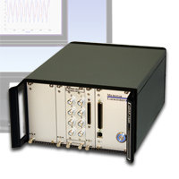
TBTSM (Time Base and Time Synchronization Module)
Time Base Synchronization
Related |
|---|
|
The TBTSM module is available as part of the Review the manual. |
When processing must be distributed among two or more measurement stations, maintaining precisely synchronized operation is tricky. The usual idea for synchronized sampling is to drive every station with the same sampling clock. However, distributing high-rate digital signals that are sufficiently clean and undistorted is not easy, even with hosts a few inches apart in the same rack. When stations must be physically separated by larger distances, this kind of solution rarely succeeds.
Things work much better when all of the stations operate autonomously and independently, aligning their sampling rate to a common reference clock, but not driving the sampling process directly. Some very good products can produce timing signals that are accurate and stable, but typically not well-suitable for sampling control. For example, a GPS receiver: it can produce a clean TTL-compatible timing pulse, but the rate is fixed at one pulse per second.
The Time Base and Time Synchronization Module (TBTSM) offers one possible strategy for time alignment with a much higher degree of flexibility.
Hardware driven timing signals
The conventional but somewhat awkward way to align sampling to a reference timing signal, using a sampling rate different from the reference pulse rate, is to use a clock multiplier scheme. A local oscillator generates a stable sequence of digital timing pulses, and counts them. The local oscillator pulses are used to clock the analog-to-digital converter hardware. In the meantime, if pulses count per timing cycle is inconsistent with the reference clock pace, some kind of comparator and a feedback heuristic will attempt to appropriately adjust the oscillator rate. This can work very well, but isn't perfect. Control loop accuracy and stability are sometimes an uneasy tradeoff, so good equipment often comes at a price.
A processing-based alternative
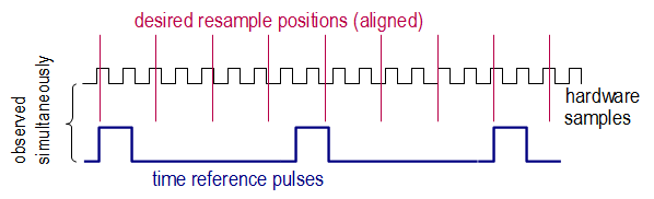
The Time Base Synchronization module supports a synchronization scheme that does not need the extra rate multiplier and control hardware. This scheme uses an abundance of samples — known as oversampling — for all signals, including the timing signal. Taking timing data and "measured signal data" side-by-side, a precise mathematical relationship can be constructed on-the-fly. This mathematical association can then be expanded to determine where samples are needed from each measured signal to be consistent with the rate defined by the time reference. Digital Signal Processing (DSP) techniques are then applied to evaluate the samples.
The illustration below shows the relationship between the high resolution hardware sampling, the sampled data that you want, and the time base signal.
Limitations of digital tracking
A fundamental limitation of digital timing signals is that the information about whether sampling rates are consistent or inconsistent with the reference clock exists only at the digital transitions. This causes problems for both the rate multiplier and digital processing schemes.
When a timing signal transition occurs, hardware must make an instantaneous heuristic rate adjustment based on the best available current information. A processing strategy can take a longer view and combine current information with past history to makes its decisions. This offers a chance to make better adjustments.
On the other hand, hardware operates in continuous time with very high time resolution. Processing can only observe clock pulses after they have been sampled, leaving no precise information to suggest where the transition might lie between the sampling instants. If the timing frequency happens to be matched perfectly, transitions are never observed early or late, so a small phase error can persist undetected. A relatively high hardware sampling rate must be configured to keep this phase uncertainty small.
Configuring a timing analysis
Incorporating synchronization processing into your data acquisition configuration requires only two added processing commands.
Here is an example how you would use the OSCSCAN processing command to perform a processing-based timing analysis when used with a generic square-wave oscillator.
OSCSCAN( IPipe7, $0001, 10.0, 2272.727272, pTiming )
- The
IPipe7input channel provides the samples of the reference timing signal taken from a digital port. - The
bitmaskspecifies that the lowest bit on the port is the one receiving the timing signal. - The hardware sampling clock captures a sample of every signal in a (nominal) 10.0 microsecond sampling interval.
- The reference timing signal is a square wave oscillator that produces a highly accurate A-440 frequency with cycle time intervals of 2272.727272 microseconds.
- Results of the timing analysis are sent to the
pTimingdata pipe.
Once the timing analysis determines where the time base pulses are located, sample values can be found relative to those pulses.
Continuing the example, here is how you could use the TBRESAMP processing command to obtain desired audio sample values at a conventional 44100 samples per second rate for two digitized signal channels, aligned to the 440 Hz oscillator used as the timing standard.
TBRESAMP( IPipes(0,1), 2, pTiming, 22.67573696145, pResampled )
- The high-rate audio samples come from two hardware sampler channels.
- The audio data is for stereo, so the number of signal channels is 2.
- The
pTimingpipe provides the timing data produced above using the 440 Hz reference time base. - The desired new sampling interval is 22.67573696145 microseconds (44100 samples per second rate.)
- Data for the two channels at the new sample rate go to the
pResampleddata pipe.
Technical performance
| preserved flat band width | 40% of Nyquist frequency at hardware rate |
| preserved band flatness | ±0.00025 dB (equivalent to ± 1 LSB) |
| time alignment | 0.0 to 1.0 hardware sampling interval |
| typical short-term frequency error | ± 2 parts in 106 |
| long-term frequency error | 0.0 |
| time reference oscillator rate | 1.0 to 10000.0 pulses per second |
More information is available in the User's Manual for the TBTSM Module.
The Time Base and Time Synchronization module is distributed as part of the DAPtools Standard software.