Software Triggering
|
|
|
|
|
|
|
Home | DAQ Techniques | Download as a PDF | View as one page
<< Previous 1 2 3 4 5 6 Next >>
Software Triggering, Part 5
Related |
|---|
|
|
Despite its speed limitations, software triggering for level detection might still be faster by a wide margin than what your PC host or a Programmable Logic Controller could do. If a response delay of one millisecond is acceptable, a Data Acquisition Processor might have the speed you need to detect critical levels AND control your processes.
Or go back to start at page 1 of Software Triggering.
Multi-Input ON-OFF Control
For this example, an automated manufacturing process will inject a carefully measured amount of liquid into a bottle, and then the bottle will be moved to the next station for subsequent processing. For purposes of filling the bottle, there is a sequence of events.
- The bottle arrives for filling, breaking the light beam of an optical sensor. Triggering on the sensor signal begins the fill process.
- Begin measuring the weight of the bottle. Each time the weight measures low, emit a pulse to request additional fluid fill and continue.
- When the weight indicates that the bottle is full, trigger to seal off the fluid flow.
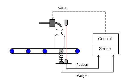
We will concentrate on the triggering. The problem here is that one sensor starts the fill operation, while a completely different sensor stops it. A Programmable Logic Controller is a suitable alternative for this application if speed requirements are moderate and you don't need to worry about high measurement precision. A PLC can give you 1/30 or 1/60 second time resolution, but a DAP board can give you 1/1000 second time resolution easily.
ON-OFF Triggering with DAPL
Suppose that the optical sensor readings come in on input
data channel IPipe0. A high-to-low change in the
signal level when the light beam is broken will indicate that a
bottle is in position.
Suppose that the weight sensor readings come in on input
channel IPipe1. It is calibrated so that the
voltage level rises as the fluid is injected, with 24000
converter counts indicating a full bottle.
The DAPL system provides a special command called
Toggle to coordinates signals from two sources.
Each source is processed in a manner similar to the
Limit command, but the signals are used one at a
time. The Toggle command skips activity on the signal it is not watching.
    TOGGLE ( IPipe0, inside, 0, 1000, \
             IPipe1, outside, -32768, 24000,   T_Fill )
The details:
- Watch
IPipe0until the voltage level from the optical sensor measures in the range 0 to 1000 counts. When this occurs, write an event to triggerT_Fill. - Ignore the
IPipe0pipe, and instead watch the weight level data from theIPipe1pipe. When this exceeds 24000 – the bottle is full – write another event to triggerT_Fill.
Responding to ON-OFF Events
The strictly alternating sequence of ON
events and OFF events in trigger T_Fill
is processed by the Toggwt command.
The Toggwt command is something like the
Wait command, but it expects alternating
events.
TOGGWT ( IPipe1, T_Fill, P_DigPort, "FORMAT=STREAM" )
The TOGGW2 command has many other output
control options besides STREAM, but streaming
output is the simplest, and it is used for this example. The
weight measurements are copied from IPipe1 into the
pipe P_DigPort starting when the ON
event arrives, and the data transfers continue until the
OFF event arrives. If the fill process is working
properly, the fill weight will increase smoothly, and the
fill process will terminate at the correct level.
The rest is beyond the scope of this article, but to
summarize briefly, the data in pipe P_DigPort
appear at regular intervals determined by samples propagating
through the processing sequence. We can replace the values of
the retained weight measurements with an alternating sequence
of values 1 and 0, term by term. These can then be used to
drive a digital output port. That controls the injection valve
solenoid.
All of the examples so far determine triggering conditions by observing signals independent of the PC host. But what if there are conditions that only the PC host can detect? We cover an example of this in the last part of the series.
<< Previous 1 2 3 4 5 6 Next >> View as one page