Software Triggering
|
|
|
|
|
|
|
Home | DAQ Techniques | Download as a PDF | View in multiple pages
Triggering: When Is It Time to Measure?
Related |
|---|
|
|
Some measurements can be taken pretty much any time, and it isn't terribly important when you start and stop. For example, if you are measuring the size of an object, it will be roughly the same size regardless of when you measure it. But not all measurement applications are like this.
For some applications, the phenomenon you need to measure is not always present. Until it is, there is no point in recording measurements. These are examples.
- Chemical reactions. When a reagent is added to a solution, things start to happen. Mix the chemicals first and then start measuring, you miss measuring the important initial phase of the reaction. Start measuring first and then mix the chemicals, and you collect lots of extraneous measurements before the relevant data.
- Synchronizing events. The power stroke of a engine follows firing events. Measuring just any old time, you are equally likely to measure a fuel injection cycle instead of a firing cycle.
- One-time or rare events. There is little point in collecting and sorting through masses of data where nothing happens.
Background: Hardware Triggering
Though this article is about software triggering, it is helpful to contrast it with hardware triggering, which is simpler, more familiar, and more limited.
If you have just the right digital electronic signal, you can use it to start (and sometimes to stop) data collection. This kind of hardware control of the measurement process is called hardware triggering.
Hardware triggering
If you don't have an appropriate digital signal, hardware triggering becomes more complicated. Some data acquisition products provide a voltage comparator amplifier for converting an analog signal into a digital form, which might be sufficient.
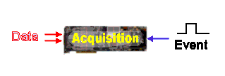
Pre-Event Data and Buffering
To record data before an event occurs, you need two things: 1) sampling that occurs whether or not events occur and 2) memory to record past measurements just in case they are needed.
Preserving data requires memory. Hardware-based schemes typically use a circular buffer configuration. In concept, special addressing logic selects memory locations for new measurements sequentially, advancing around a circle. By recovering stored values from the circular buffer, you can obtain measurements preceding the time of an event.
When an event signal arrives, the hardware records the address of the most recent sample value, placing this address in a special event register. Also, the hardware informs the host of the event, to let it know that it had better do something – fast!
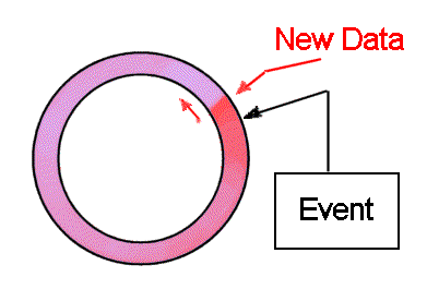
Circular buffering scheme
Actual memory addresses are not circular, rather they are linear up to some maximum, at which point there is a sudden "address wrap around" to zero. Hardware devices typically leave the host software with the burden of tracking the wrapping behavior and dynamically unwrapping it to select stored values.
The circular buffer scheme is highly dependent on software to respond to signals for events, determine how to address the data, and fetch data across the data bus into host memory. There is a race condition, and any delay in responding to the hardware event signal results in overwriting and loss of some of the buffered data.
Software Triggering
Rather than using hardware circuits to determine when to measure, it is tempting to configure a software program and let it determine when to measure. This is the idea behind "software triggering."
Software triggering leads to a kind of "chicken or egg" paradox. You don't want the measurements captured until you trigger; but there is no point in triggering until you know you want the measurements!
Most data acquisition software that claims to support "software triggering" merely initiates the triggering action using a software command. This leaves you with the decision about when to issue this command – back to the "chicken or egg" paradox. Without seeing the data, how can you know whether you want to trigger or not?
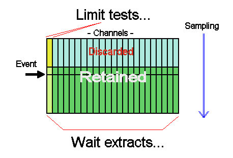
The DAPL system breaks the paradox much as hardware circular buffering does. Measurement activity is started well in advance of capturing data. Past data are retained in memory buffers, and the DAPL system manages the data memory. You don't need to worry about how, and you don't need to worry about data locations. Unused data are automatically released to make storage available for new data. The buffering is completely automatic, and can expand to the limits of available memory as needed. There is never a race condition, and new data can never overwrite old data despite any delays that might occur.
The principal advantage of the DAPL software triggering is that you can analyze data and detect events intelligently, directly in buffer memory. All of this takes place on the Data Acquisition Processor board, without transferring anything to the host PC. This doesn't eliminate the need to scan through masses of data looking for events, but it avoids overloading your host with intense data transfers and computations when there is nothing of interest.
For detecting and reporting events, the DAPL system keeps a
streaming record of event locations in a queuing mechanism
called a trigger pipe. You can extract the
information about events in much the same way that you would
read from a data stream.
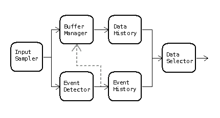
Software triggering scheme
There is one drawback to software triggering. A trigger event determines the location of interesting data in a continuing stream of data, but does not initiate responsive action. There remains a time lag until the event is processed. If you need fast real-time response, software triggering is probably not the right tool for the job.
Triggering: How Do You Use It?
Related |
|---|
|
|
To add software triggering to a data acquisition application on a Data Acquisition Processor system, you will add the following additional features to your configuration.
- Define a
triggerto preserve information about detected events. - Define a trigger-writing task to detect events.
- Define a trigger-reading task to respond to the events and perform the processing you want.
- Define a pipe to receive the selected data.
It is presumed here that the application is configured
for input sampling. The sampling configuration can have any
number of channels, and you can pick any channel you want to
detect events. Here, we will presume that triggering scans the
contents of the first channel pipe IPipe0.
We also assume that you are preparing your configuration with
the assistance of the DAPstudio program.
Defining the Trigger and Pipe
A trigger preserves the information about
where in a data stream an event is detected. You can define
a trigger in DAPstudio under the Processing tab
and its Declarations sub-tab.
trigger T_VHigh mode=normal
Define a pipe to receive the selected
data on the same Declarations sub-tab.
pipe P_Select word
Define Processing to Detect Events
Define the processing task that makes the data selection. The possibilities are limitless... but this article covers only the simple case that an extreme signal level indicates an event of interest. Presume that any value higher than +25000 indicates that an event has occurred.
In DAPstudio, select the Processing tab and the Procedure sub-tab. Enter the command name Limit and then an open parenthesis in the task configuration editor. DAPstudio will guide you through the entry of the following task parameters.
Limit(P_Select,inside,25000,32767,T_VHigh,inside,25000,32767)
-
IPipe0
– This is the data channel that will be scanned for events. -
inside
– Begins the definition of the data range that indicates an event. -
25000
32767
– These two parameter define the limits of the range that indicate the event. -
T_VHigh
– Specify the trigger you just defined to receive the event notifications. -
inside
25000
32767
– These three parameters define a lockout range. Until the signal level drops out of this range, no additional events will be recorded.
Define Processing to Respond to Events
Let us suppose that the desired action is to capture 100
samples prior to the event and 924 samples from the event
onward, for a total of 1024 samples. To do this, use another
pre-defined processing command called Wait.
Enter this command line in the processing configuration.
The DAPstudio program will assist you as you enter the following
task parameters.
Wait(IPipe1,T_VHigh,100,9024,P_Select)
-
IPipe1
– This is the data stream from which data are selected. -
T_VHigh
– Specify the trigger with the information about events. -
100
9024
– Specify the number of samples before the event, and the number of samples from the event onward, to be extracted. -
P_Select
– Tell the command where to place the selected data.
You will typically go to the Send to PC tab, de-select the usual input channels, and select the retained data pipe (in our example, P_Select) for transfer to the PC host.
Your application is configured and ready to test. Once you have the configuration set up correctly, you can copy it into any software application you want, from an embedded application that you write yourself, to a monster GUI application with every conceivable kind of graphical displays and user controls. The performance is embedded in the data acquisition processor.
Use Software Triggering to Process Data in Blocks
Once software trigger events are detected they are... in software. This gives the flexibility to do some things easily that would otherwise be enormously difficult, perhaps impossible. Applications can use software triggering to process data in blocks rather than individual samples.
Selecting Data in Blocks
Related |
|---|
|
|
Suppose for example that data are captured at 1 million
samples per second. 2048 samples are selected for
processing by an FFT command every 0.1 second, producing
1024 magnitude output terms per input block of 100000 terms.
Most of the time, nothing happens and the FFT data can be
discarded. To this point, no triggering is needed. Just use
a SKIP command to retain the first 2048 samples
from each block of 100000 input samples, route this data
for processing by the FFT, and discard the rest.
Most of the time, nothing happens. However, if an event occurs any time within the 0.1 second interval spanned by a block of 100000 samples, three FFTs are computed. One FFT is applied to the first 2048 samples from the current block. The other FFTs are applied to the first 2048 samples from the preceding block, and to the first 2048 samples from the block to follow. How can you do this?
Thinking about this in terms of blocks, it is relatively easy. For example, if the event occurs in the input block 5 (input samples 500000 through 599999), you want to keep the FFT results for blocks 4, 5, and 6. You can determine the input block number easily from the event location.
(event location) / 100000
One FFT every 1/10 second is easy for a DAP board to do. So instead of worrying about when to perform the FFT operations, it is easier just to stream each 2048 point data block into FFT processing as it arrives. The resulting blocks of 1024 FFT output values stream out. If an event occurs, you keep the resulting FFT blocks, otherwise they are discarded. The locations of desired FFT results in the FFT output stream are calculated easily.
(block number) * 1024
Processing Implementation
All of this theory is fine, but event locations are not
the same as ordinary data. How can you apply these calculations
to events? Easily, as it turns out. The DAPL system provides
a command called TRIGSCALE that takes a trigger
input derived from analyzing data at one rate, and produces
from it a new trigger event that operates at a different
data rate. Use the modified event locations when selecting
data from the FFT output stream.
Here are the configuration lines that you would use.
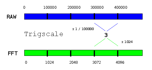
  Trigscale( RAWtrig, 0, 1024, 100000, FFTtrig )
  Wait( FFTresults, FFTtrig, 1024, 2048, FFTselected )
The details:
- Analyzing the original sample stream produces events in trigger
RAWtrig, as described previously. - The
Trigscalecommand takes an event location from triggerRAWtrig, without any offset adjustment, and divides by 100000. It truncates the fraction to produce the input block number. - The
Trigscalecommand then takes that intermediate result and multiplies it by 1024 to obtain the location of the associated FFT output data block, placing this new event location into triggerFFTtrig. - The
Waitcommand selects data from the FFT output stream in the usual manner, using the locations from theFFTtrigtrigger, and placing the data into transfer pipeFFTselected.
Extensions
In this example, the application captures data when it observes something interesting. However, it is not completely rigorous about capturing all data where anything interesting occurs. If the last block analyzed for an earlier event happens to contain a new event, it will be impossible to respond to this event properly. The data for the "block prior" was taken by previous processing. The DAPL system cannot partially respond, which means that the FFT block following the secondary event will be missed.
You can be sure that all events are covered if you use
the DEFERRED
operating mode and HOLDOFF properties (link opens 1.27MB PDF manual) when
you declare trigger FFTtrig command in your
processing configuration.
Multiple Channel Acquisition with Triggering
The application is a vehicle crash test. You will observe data for stress, buckling, and fractures at 100 sensor locations on an instrumented vehicle – and in a fraction of a second it is all over.
You have just one chance to capture the measurements. There is too much data to collect it all continuously, but you cannot afford to miss any relevant data or risk drowning your system with irrelevant data before the crash event has occurred.
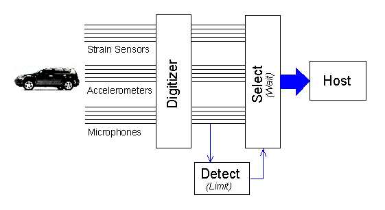
Suppose that you are using a DAP 5400a/627, sampling 8 channels simultaneously, with each of the 100 channels sampled at each 100 microsecond interval. During an experiment covering 0.5 seconds, you will collect about 4 million samples. The host interface can transfer about 2.5 million samples under ideal circumstances. Depending on what your application processing does with the data, you might be able to move perhaps 1 million samples into your application software during the event. The other 3 million samples are captured and buffered on the DAP, and sent when the host software is able to accept them.
Reliable Triggering
Related |
|---|
|
|
A high-speed transient glitch propagating along a sensor wire could easily set off an electronic triggering circuit. A glitch of that kind would not be persistent. The real signals of a crash event would be very different. When using software triggering, you can combine processing with triggering, so that real events are distinguished from the meaningless noise glitches.
Suppose you select one of the microphone channels that
will respond to early contact, and connect it to signal
channel IPipe0. You don't want DC offsets on this channel to
make the triggering too sensitive or too insensitive. You
can use a running average over a long time window to
approximate the offset level for cancelling it.
On the other hand, you don't want a single "spike" to prematurely trigger. You can use a running average with a short time window to smooth out noise spikes. To trigger, the signal must reach the triggering level and stay there for a few samples.
The following configuration cancels DC offsets, smoothes out spikes, and triggers when the signal level deviates from the baseline level consistently through a window of 7 samples.
   pipes  pDCoff word, pCleaned word
   pipes  pDiff
   trigger   tCrashEvent
   ...
   pdefine  CrashCapture
     raverage(IPipe0, 400, pDCoff)
     raverage(IPipe0, 7, pCleaned)
     pDiff = pCleaned - pDCoff
     ...
Now you can trigger reliably on the processed pDiff signal, as described in other parts of this article.
     Limit( pDiff, OUTSIDE, -20000, 20000, tCrashEvent )
     ...
Accounting for Many Channels
The crash is detected on just one channel, but data are collected in many channels. As we saw earlier, the position of the data in a triggering channel must be used to determine the associated position of the data in channels where data are taken.
The Wait command makes this very easy. When
you capture data from multiple channels of an input channel
pipe, the DAPL system will automatically account for the number
of samples in the individual triggering channel and in the
multiplexed channel pipe. You can select extra samples from
just before the crash to establish a statistical baseline, and
then capture the 4 million samples for the crash event. The
complete set of samples is sent straight to the host system.
    ...
    Wait(IP(0..99), tCrashEvent, 12000, 4000000, $Binout)
  end
Intelligent Triggering
Related |
|---|
|
|
Despite its speed limitations, software triggering might still be faster by a wide margin than what your PC host or a Programmable Logic Controller could do. If a response delay of one millisecond is acceptable, a Data Acquisition Processor might have the speed you need to measure AND control your processes.
Multi-Input ON-OFF Control
For this example, an automated manufacturing process will inject a carefully measured amount of liquid into a bottle, and then the bottle will be moved to the next station for subsequent processing. For purposes of filling the bottle, there is a sequence of events.
- The bottle arrives for filling, breaking the light beam of an optical sensor. Triggering on the sensor signal begins the fill process.
- Begin measuring the weight of the bottle. Each time the weight measures low, emit a pulse to request additional fluid fill and continue.
- When the weight indicates that the bottle is full, trigger to seal off the fluid flow.
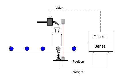
We will concentrate on the triggering. The problem here is that one sensor starts the fill operation, while a completely different sensor stops it. A Programmable Logic Controller is a suitable alternative for this application if speed requirements are moderate and you don't need to worry about high measurement precision. A PLC can give you 1/30 or 1/60 second time resolution, but a DAP board can give you 1/1000 second time resolution easily.
ON-OFF Triggering with DAPL
Suppose that the optical sensor readings come in on input
data channel IPipe0. A high-to-low change in the
signal level when the light beam is broken will indicate that a
bottle is in position.
Suppose that the weight sensor readings come in on input
channel IPipe1. It is calibrated so that the
voltage level rises as the fluid is injected, with 24000
converter counts indicating a full bottle.
The DAPL system provides a special command called
Toggle to coordinates signals from two sources.
Each source is processed in a manner similar to the
Limit command, but the signals are used one at a
time. The Toggle command skips activity on the signal it is not watching.
    TOGGLE ( IPipe0, inside, 0, 1000, \
             IPipe1, outside, -32768, 24000,   T_Fill )
The details:
- Watch
IPipe0until the voltage level from the optical sensor measures in the range 0 to 1000 counts. When this occurs, write an event to triggerT_Fill. - Ignore the
IPipe0pipe, and instead watch the weight level data from theIPipe1pipe. When this exceeds 24000 – the bottle is full – write another event to triggerT_Fill.
Responding to ON-OFF Events
The strictly alternating sequence of ON
events and OFF events in trigger T_Fill is processed by the Toggwt command.
The Toggwt command is something like the
Wait command, but it expects alternating
events.
TOGGWT ( IPipe1, T_Fill, P_DigPort, "FORMAT=STREAM" )
The TOGGW2 command has many other output
control options besides STREAM, but streaming
output is the simplest, and it is used for this example. The
weight measurements are copied from IPipe1 into the
pipe P_DigPort starting when the ON
event arrives, and the data transfers continue until the
OFF event arrives. If the fill process is working
properly, the fill weight will increase smoothly, and the
fill process will terminate at the correct level.
The rest is beyond the scope of this article, but to
summarize briefly, the data in pipe P_DigPort
appear at regular intervals determined by samples propagating
through the processing sequence. We can replace the values of
the retained weight measurements with an alternating sequence
of values 1 and 0, term by term. These can then be used to
drive a digital output port. That controls the injection valve
solenoid.
Host-Triggered Measurement
Software triggering can allow intelligent decisions about when to capture meaningful data, without any intervention from the host system. But there are times when only the host system knows when it is appropriate to measure.
In most data acquisition systems, the software triggering is just a slow means for activating hardware triggering across a host interface bus. With a Data Acquisition Processor board, the same kind of triggering is available, and it remains slow. The bus interface is fast, but it has unpredictable setup delays. There is nothing that can be done about this.
For example, suppose that the purpose of a test is to measure how well shielding material protects against hard impacts.
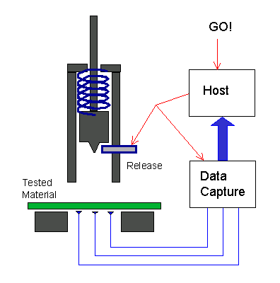
There is no point in collecting impact data until the firing mechanism is ready for release. The PC host could activate the release mechanism and at the same time tell the Data Acquisition Processor to expect the event. The problem is, the signals to the release mechanism and to the DAP take different hardware signal paths, and the operating system delays for delivering the messages on each channel are unpredictable.
Suppose that the following timing constraints apply:
- The setup delay to send a new message to the Data Acquisition Processor is 0 to 25 milliseconds.
- The setup delay in signalling the release mechanism is 0 to 25 milliseconds.
- The time delay to reach impact is 5 milliseconds.
- The impact event finishes in 10 milliseconds.
- The sampling rate is 1000000 samples per second.
The following diagram illustrates the two most extreme cases for timing.
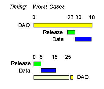
In the first case, the Data Acquisition Processor receives its notification almost immediately, while the release mechanism message is delayed 25 milliseconds. The DAP will not start to see any meaningful data until 30 milliseconds later. In the second case, the release mechanism receives its message 25 milliseconds ahead of the DAP, and the entire experiment is completed 10 milliseconds before the DAP is notified.
To make sure that the DAP captures all of the data in the case that its notification arrives late, it should retain data starting 20 milliseconds before its notification time. To make sure that the DAP captures all of the data in the case that its notification is early, it should continue to retain data until 40 milliseconds after the notification. The total data collection interval is 60 milliseconds, and 60000 samples are collected.
Converting Messages to Events
Related |
|---|
|
|
A message is easily transferred from PC host software into
the Data Acquisition Processor using pre-defined communication
pipe $Binin . In the following application coding
example, the DAP_outhandle variable points to
the $Binin pipe, and the transfer value is taken
from the arbitrary buffer – in this case,
a 2-byte integer variable. The value doesn't matter. It is the
transfer that signals the external event.
DapBufferPut( DAP_outhandle, 2, &arbitrary );
When this number reaches the Data Acquisition Processor, an
event is constructed in the software trigger T_PCevent
using the PCASSERT command.
PCASSERT( $Binin, T_PCevent )
The PCASSERT command solves the problem of determining the
position in a data stream when the input data come from an
external source. It assigns an event position based on the
current sample count of the sampling process.
For the impact test example, after the trigger event is
posted, a WAIT command can be applied in the DAPL
configuration as usual, preserving 20000 samples before the
event and 40000 samples after the event.
WAIT( IPipe0, T_PCevent, 20000, 40000, $Binout )
Extensions
In the example, a captured data set will include 60000
samples, of which only 10000 are relevant. The rest allow
for the uncertainties in PC host timing. Intelligently isolating
relevant data is the specialty of software triggering. The fact
that the selected data came from a triggering process
doesn't matter. You could apply an additional LIMIT
and WAIT command pair as described in
previous sections to isolate the relevant parts.
An alternative solution is to let the DAP detect
the impact event by testing a data channel in the usual manner.
To prevent extraneous triggering events between experiments,
use the TRIGARM command to disable triggering
until the next experiment is ready.
This concludes the article on software triggering, but hardly exhausts all of the possibilities. Some additional topics covered in the manuals but not covered here include:
- logic to coordinate and merge event sequences from multiple sources
- using software triggering on multiple slaved boards
- custom programming of trigger processing commands
A Data Acquisition Processor board can be an excellent platform for technologies and techniques beyond the scope of this article. Take a look at other data acquisition and control techniques. Or take DAPstudio out for a spin.