Configuring Differential Current Sense Inputs
Technical Note TN-255 Version 1.0
The manuals for the MSXB037 Analog Input Expansion board and MSTB009 Analog Termination board describe how to configure an input for 0-20mA current sense measurements. These instructions refer only to single-ended measurements, which means that one end of the signal must be connected directly to ground.
Sometimes, though, the current sense measurement needs to be isolated from the system ground. This can be accomplished by measuring the signal differentially. This technical note describes how the MSXB037 and MSTB009 can be configured for this type of measurement by connecting the current sense resistor across the inputs of one of the eight available differential channels (Dn+, Dn-).
The high input impedance of the DAP effectively removes any direct ground connection. Because the DAP's A/D circuitry requires a ground reference, a high-value resistor must be connected between each of the signal's Dn terminal and its respective ground (Gn) terminal. The common-mode input range of a DAP is typically +/-12V. This means that if the current signal is not completely isolated from ground, any offset must be within +7 to -12 V or clipping will occur.
The following instructions describe how to configure the D0 input for differential current sense measurement. The remaining differential channels may be similarly configured using the following substitutions:
| Channel | Gnd Resistor - | Gnd Resistor + | Input | Input + |
|---|---|---|---|---|
| D0 | R1 | R3 | S0 | S1 |
| D1 | R5 | R7 | S2 | S3 |
| D2 | R9 | R11 | S4 | S5 |
| D3 | R13 | R15 | S6 | S7 |
| D4 | R17 | R19 | S8 | S9 |
| D5 | R21 | R23 | S10 | S11 |
| D6 | R25 | R27 | S12 | S13 |
| D7 | R29 | R31 | S14 | S15 |
Table 1: Channel Substitutions
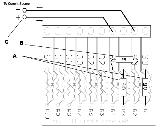
Install the three resistors as shown. No other modification of the MSXB037 or MSTB009 is required.
- Install 2x 1M ohm ground reference resistors (resistance code '105') in the R1 and R3 locations as shown below. High precision resistors should be used to get the best accuracy and common mode rejection.
- Install 1x 250 ohm current sense resistor (resistance code '251') in the pads directly below the S1 and S0 labels as shown. Place the resistor in such a way that the body will not come into contact with the lead of the 1M resistor below it.
- Connect the 0-20mA signal to the S1 (+) and S0 (-) inputs. The current should flow through the current sense resistor in the direction shown.

Figure 1: Connections for Differential Current Sense Measurements
View other Technical Notes.