MSXB 039 Opto-Isolator Board
Technical Note TN-192 Version 1.0
The Microstar Laboratories Opto-Isolator Board, part number MSXB 039, has provisions for up to eight opto-isolation modules. The Opto-Isolator Board accepts Generation 4 series modules manufactured by OPTO-22. These modules sense or switch high voltages and currents that a Data Acquisition Processor™ cannot handle directly. Input modules are used for sensing ON/OFF voltage levels. Output modules are used for switching high voltages and currents.
The Opto-Isolator Board is compatible with all a-Series and e-Series Data Acquisition Processors. The Opto-Isolator Board is connected to a Data Acquisition Processor through its digital port. There are sockets for eight modules on the Opto-Isolator Board. Any socket may contain either an input module or an output module, independent of the other sockets. Using four Opto-Isolator Boards without digital expansion addressing, up to 16 input modules and 16 output modules can be connected to one Data Acquisition Processor. Using multiple Opto-Isolator Boards with digital expansion addressing, up to 128 input modules and 1024 output modules can be connected to one Data Acquisition Processor.
Input and output modules are available in several AC and DC voltage ranges. Modules can be selected with voltage ranges that best fit an application. Contact your Microstar Laboratories product supplier for a list of compatible modules.
Hardware Configuration
The Opto-Isolator Board is connected to the Data Acquisition Processor with a 100-line cable adapter board, part number MSCBL 046-01 and a 100-line cable, part number MSCBL 054-01 or part number MSCBL 056-01. The cable adapter board attaches to the Digital Input/Output Port of the Data Acquisition Processor, and the 100-line cable connects the cable adapter board to connector J1 of the Opto-Isolator Board.
The Opto-Isolator Board also may be connected directly to the Digital Input/Output Port of the Data Acquisition Processor with a 100-line adapter ribbon cable, part number MSCBL 058-01.
Warning: Never connect or disconnect the Opto-Isolator Board while the Data Acquisition Processor is powered. Also never connect or disconnect any of the modules while the Opto-Isolator Board is powered.
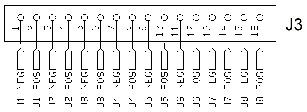
Connections are made to the modules on the Opto-Isolator Board by means of either the 16-point quick-connect termination (J3) or the optional 50-line connector (J2). The pin numbering and signal connections of J3 are shown in Figure 1.

Figure 1. Quick-Connect Termination
If DC modules are used, the connections to the Opto-Isolator Board must be made so that the voltage at the positive terminal is always greater than the voltage at the negative terminal. When using AC modules, the positive and negative terminals are interchangeable and the polarity does not matter.
Caution: If high voltages are connected to the Opto-Isolator Board, extreme caution should be used to prevent electric shock. Always disconnect all high voltages before handling the Opto-Isolator Board. Mount the Opto-Isolator Board so that it cannot come into contact with conductive materials.
Input or Output Module Selection
Jumpers J11 through J18 select between input and output modules for the individual sockets. Figure 2 shows the shunt positions for input and output module configurations as seen from the front of the Opto-Isolator Board. J11 corresponds to socket U1, J12 to U2, and so on. Table 1 shows the correspondence between jumpers and modules.

Figure 2. Input and Output Selection
The 16-bit input and output ports of the Data Acquisition Processor are divided into two halves on an Opto-Isolator Board. Either the low-order or the high-order half of each port is connected to the modules. If the low-order half of the port is selected, bit 0 is connected to module U1, bit 1 is connected to U2, and so on. If the high order half of the port is selected, bit 8 is connected to module U1, bit 9 is connected to U2, and so on. Table 1 shows the bit mapping and jumper locations for each configuration.
Module Jumper Low-Order High-Order U1 J11 Bit 0 Bit 8 U2 J12 Bit 1 Bit 9 U3 J13 Bit 2 Bit 10 U4 J14 Bit 3 Bit 11 U5 J15 Bit 4 Bit 12 U6 J16 Bit 5 Bit 13 U7 J17 Bit 6 Bit 14 U8 J18 Bit 7 Bit 15 |
Even if input and output modules are mixed on a single Opto-Isolator Board, the bit connections explained above remain the same. The input configuration applies only to the input modules and the output configuration applies only to the output modules.
For example, suppose U1 through U6 are output modules and U7 and U8 are input modules. Also suppose both the input and output ports are configured for the low-order half of the digital port. With the Opto-Isolator Board configured in this way, output bits 0 through 5 control modules U1 through U6. Input bits 6 and 7 are connected to modules U7 and U8, respectively. Output bits 6 and 7 and input bits 0 through 5 are not connected in this case. The input and output ports can be configured independently for low-order operation or high-order operation.
By configuring the shunts on header J4, the user can select the half of each port that is used. The input port is configured by the upper shunt while the output port is configured by the lower shunt. Figure 3 shows each of the four possible combinations of shunt positions. Removing the input shunt disables all inputs and removing the output shunt disables all outputs.

Figure 3. Input/Output Selection Options
Digital Expansion Settings
The Opto-Isolator Board can be configured to work with or without digital expansion addressing. By configuring J8, the user can enable or disable digital expansion addressing. Figure 4 shows the possible combinations for J8.

Figure 4. Digital Expansion Addressing
When digital expansion addressing is disabled, the Opto-Isolator Board ignores the digital expansion address lines and acts as if the modules were directly connected to the input and output lines of the Data Acquisition Processor Digital Input/Output Port. Up to four Opto-Isolator Boards with addressing disabled can be used per Data Acquisition Processor. Two boards may be used for input (one low-order and one high-order) and two boards may be used for output (one low-order and one high-order).
Warning: When using Opto-Isolator Boards with digital expansion addressing disabled, no other boards should be connected to the Digital Input/Output Port of the Data Acquisition Processor.
When digital expansion addressing is enabled, the Opto-Isolator Board uses the same digital expansion scheme as the Digital Expansion Board. Using this scheme up to 16 Opto-Isolator Boards can be used for input and 128 Opto-Isolator Boards can be used for output. Also when using the digital expansion scheme, other expansion boards may be used on the Data Acquisition Processor's Digital Input/Output Port in conjunction with the Opto-Isolator Boards.
Input Address Selection
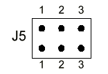
When using the digital expansion scheme, each Opto-Isolator Board that is to be used for input must be configured to recognize a specific input address. When inputs are enabled then header J5 selects this input address.

Figure 5. Input Address Selection Header
The input address is selected according to the following table:
Input Range      J5 Jumpers
    B0            3, 2, 1
    B1            3, 2
    B2            3, 1
    B3            3
    B4            2, 1
    B5            2
    B6            1
    B7            none
|
A shunt on header J4 is used to select the high-order or low-order byte of the input address. To disable inputs remove this input shunt from J4.
Warning: No more than one board should have its inputs enabled for each input address and byte order. If more than one board share the same input address and byte order with their inputs enabled the system may be damaged.
Output Address Selection
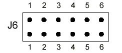
When using the digital expansion scheme, each Opto-Isolator Board that is to be used for output must be configured to recognize a specific output address. When outputs are enabled header J6 selects the output address.

Figure 6. Output Address Selection Header
The output address is selected according to the following table:
Output Address   J6 Jumpers         Output Address   J6 Jumpers
      0          6, 5, 4, 3, 2, 1         1          6, 5, 4, 3, 2
      2          6, 5, 4, 3, 1            3          6, 5, 4, 3
      4          6, 5, 4, 2, 1            5          6, 5, 4, 2
      6          6, 5, 4, 1               7          6, 5, 4
      8          6, 5, 3, 2, 1            9          6, 5, 3, 2
      10         6, 5, 3, 1               11         6, 5, 3
      12         6, 5, 2, 1               13         6, 5, 2
      14         6, 5, 1                  15         6, 5
      16         6, 4, 3, 2, 1            17         6, 4, 3, 2
      18         6, 4, 3, 1               19         6, 4, 3
      20         6, 4, 2, 1               21         6, 4, 2
      22         6, 4, 1                  23         6, 4
      24         6, 3, 2, 1               25         6, 3, 2
      26         6, 3, 1                  27         6, 3
      28         6, 2, 1                  29         6, 2
      30         6, 1                     31         6
      32         5, 4, 3, 2, 1            33         5, 4, 3, 2
      34         5, 4, 3, 1               35         5, 4, 3
      36         5, 4, 2, 1               37         5, 4, 2
      38         5, 4, 1                  39         5, 4
      40         5, 3, 2, 1               41         5, 3, 2
      42         5, 3, 1                  43         5, 3
      44         5, 2, 1                  45         5, 2
      46         5, 1                     47         5
      48         4, 3, 2, 1               49         4, 3, 2
      50         4, 3, 1                  51         4, 3
      52         4, 2, 1                  53         4, 2
      54         4, 1                     55         4
      56         3, 2, 1                  57         3, 2
      58         3, 1                     59         3
      60         2, 1                     61         2
      62         1                        63         none
|
A shunt on header J4 is used to select the high-order or low-order byte of the output address. To disable outputs remove this output shunt from J4.
Termination Resistor Networks
The Opto-Isolator Board has two socketed termination resistor networks, RN5 and RN6, adjacent to J1. The resistors are installed in the sockets when the board is shipped from the factory. For single board systems, the resistors should remain installed. For multiple board systems, only one board may have the resistors installed. The board farthest from the Data Acquisition Processor should have the resistors installed. If more than one board in a system has the resistors installed, the system may fail.
Software Configuration
An output module operates as a switch and is either on or off, depending on the state of its control bit. A bit value of 1 turns a module on (closes the switch) while a bit value of 0 turns a module off (opens the switch). An input module returns a bit value of 1 if a voltage is present and a bit value of 0 if no voltage is present. Every bit from the unused half of the input port has a bit value of 1. Table 1 shows the correspondence between bits and modules. Output modules are controlled by writing to the digital output port. Input modules are sampled by reading data from the digital input port. The bit mapping shown in Table 1 applies for both input and output modules.
Opto-Isolation Module Input
An AC input module can be used to detect the state of a light bulb. In this example an AC input module is connected across the terminals of a light bulb and is configured for input bit 0. The following DAPL commands read digital input port B0 and extract consecutive values of bit 0. If the light bulb is off, there is zero voltage across the light bulb and values of 0 are sent to the PC. When the light bulb is on, a voltage is present and values of 1 are sent to the PC.
   RESET
   PIPE P1
   IDEF A 1
      SET IP0 B0
      TIME 10000
      END
   PDEF B
      P1 = IP0 & 1
      FORMAT (P1)
      END
   START A,B
When using digital expansion addressing the SET command should specify the input port address of the board.
Opto-Isolation Module Output
In this example, a DC output module configured for output bit 4 is used to drive a DC solenoid. The following commands illustrate using digital output to control the solenoid with an output module. A value of 1 on bit 4 causes the output module to close its switch and activates the solenoid. A value of 0 on bit 4 deactivates the solenoid.
   RESET
   PIPE P1
   PDEF B
      DIGITALOUT(P1,0)
      END
   START B
   FILL P1 16
To use digital expansion addressing the DAPL command OUTPORT is required. The output port type of the Opto-Isolator Board is zero.
Synchronous Output Expansion
Synchronous digital expansion uses a special protocol which is implemented by the DAPL command DEXPAND. For each word of output, the data and address are encoded into four words that are sent to the digital output port. If DEXPAND is used, all module outputs are synchronous on all Opto-Isolator Boards. See the description of DEXPAND in the DAPL manual.
External Power Option
On MSXB 039 boards with external power, connector J7 provides the connection for external power. Connector J7 is a single row header on 0.156-inch centers. J7 is Molex part number 26-60-4030, which mates with Molex part number 09-50-3031. Each MSXB 039 without modules requires 0.53 Amps at +5 Volts DC.

Figure 7. Optional External Power Connector
Note: It is best to power the MSXB 039 from the host PC's power supply so that both the Opto-Isolator Board and the DAP are po wered on and off at the same time. If this is not practical, then external power to the Opto-Isolator Board should be applied before powering on the DAP and should be disconnected after powering off the DAP.
50-line Cable Connector Option
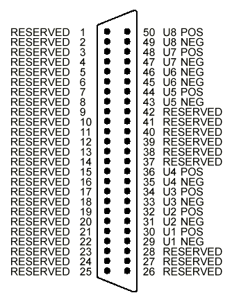
The MSXB 039 Opto-Isolator Board is available with a 50-line cable-connector option installed as connector J2. This connector provides access to the Opto-22 modules. The pin numbering and signal connections of J2 are shown below.

Figure 8. Optional 50-line Connector
Warning: When the 50-line cable connector is installed the maximum voltage difference between any two signals connected to the 50-line cable connector or the quick-connect termination is reduced to 30 Volts. Also the maximum current through each pin on the connector is 1 Amp.
External Enclosure Option
The MSXB 039 Opto-Isolator Board is available with a single-board external enclosure option. The external enclosure provides shielding and is compatible with the European Community directive 89/336/EEC.
The single-board external enclosure has several possible end panels that allow for different connection points to the Opto-Isolator Board. Contact Microstar Laboratories for more information on available end panels for the MSXB 039.
Backplane Connector Option
A MSXB 039 Opto-Isolator Board is available with a backplane connector installed at J1 instead of a cable connector. This allows the MSXB 039 to be used with a Digital Backplane.
Connector J1 of the Opto-Isolator Backplane Board plugs directly into an empty slot on the Digital Backplane. See the Digital Backplane manual for more information on how to install backplane boards into a Digital Backplane and how to connect the Digital Backplane to the Data Acquisition Processor.
Warning: Never connect or disconnect the Opto-Isolator Backplane Board while the Digital Backplane is powered.
The MSXB 039 Opto-Isolator Backplane Board has several possible front panels that allow for different connection points to the board. Contact your Microstar Laboratories product supplier for more information on available front panels for the MSXB 039.
The termination resistor networks, RN5 and RN6, are not installed on the backplane models of the MSXB 039.
View other Technical Notes.