MSXB 030 Analog Backplane
Technical Note TN-185 Version 1.2
The Microstar Laboratories Analog Backplane allows easy analog input expansion for large systems. The Analog Backplane provides expansion slots to accommodate compatible analog external boards. The Analog Backplane is passive, and connects all signals in each of the expansion slots in parallel.
The Full-Size Analog Backplane, part number MSXB 031, provides 21 expansion slots. The Half-Size Analog Backplane, part number MSXB 030, provides 10 expansion slots. All expansion slots are identical.
The Full-Size Analog Backplane is compatible with any VME standard subrack enclosure that has the following dimensions: 84-HP length, 3U height, and 220mm depth.
The Half-Size Analog Backplane is compatible with any VME standard subrack enclosure that has the following dimensions: 42-HP length, 3U height, and 220mm depth.
Installation
Analog Backplanes are often used in conjunction with Industrial Enclosures. When an Industrial Enclosure system is shipped from Microstar Laboratories, a backplane is installed.
Warning: Never install a board into the Analog Backplane or remove a board from the Analog Backplane while the Analog Backplane is powered.
An MSXB 029 Analog Backplane Interface Board must be installed in one of the Analog Backplane expansion slots. The Analog Backplane Interface Board provides expansion signals for the Analog Backplane and interfaces the backplane with a Data Acquisition Processor.
When an analog Industrial Enclosure system is shipped from Microstar Laboratories, an Analog Backplane Interface Board is installed. Please refer to the MSXB 029 documentation for more information on the Analog Backplane Interface Board.
To Install an External Board in the Analog Backplane:
- Push the board firmly into the slot and make sure the board is securely connected to the backplane.
- Secure the front panel of the external board to the Industrial Enclosure with the screws provided with the board.
Hardware Configuration
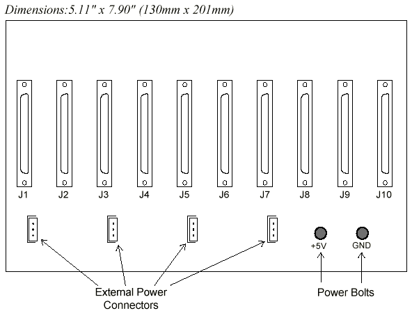
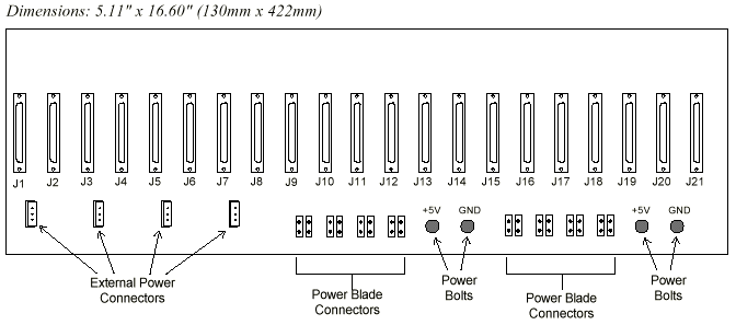
The following two diagrams show the configuration of the Half-Size and Full-Size Analog Backplanes.

Figure 1. MSXB 030: Half-Size Analog Backplane

Figure 2. MSXB 031: Full-Size Analog Backplane
Power Consumption
The Analog Backplane provides power to each slot by means of three voltage supplies: +5V, +18V, and -18V. If the total power consumption of all external boards installed in the Analog Backplane does not exceed the DAP's power availability, the Analog Backplane can draw power from the DAP via the MSXB 029-01-E2A Analog Backplane Interface Board. If the total power consumption exceeds this limit, external power must be supplied to the Analog Backplane, and the MSXB 029-02-E2A model of the Analog Backplane Interface Board must be used instead.
A Data Acquisition Processor can typically supply a total of 10W of power to all accessories products through its +5V supply. This means a DAP can supply 2A of current at +5V. Please refer to the DAP hardware documentation for more specific information on the power availability of each DAP model.
Calculating Power Consumption
To calculate to the total power consumption of a backplane system, add all the currents that each external board draws from the each voltage supply. Please refer to the documentation of each external board for power consumption requirements.
Convert the current drawn from each voltage supply to power consumption by multiplying the current by the voltage. For example, the current drawn from the +5V supply is multiplied with 5V to get the power consumed from that supply.
The power consumed from the +18V and -18V supplies needs to be divided by 0.8 to account for the 80% efficiency of the power conversion on the Analog Backplane Interface Board. Finally, add up all the power consumed from each voltage supply. The final result is the total power consumption of the backplane system.
Backplane Power Options
The MSXB 029-01-E2A model of the Analog Backplane Interface Board uses power from the DAP's +5V supply to generate the +18V and -18V supplies and provides them for the Analog Backplane. The MSXB 029-01-E2A model also distributes the DAP's +5V supply directly to Analog Backplane.
If external power is required, the MSXB 029-02-E2A model of the Analog Backplane Interface Board must be used. With this model, the DAP's +5V supply is separated from the backplane's +5V supply. An external +5V supply must be connected to the Analog Backplane through power connectors or through the power bolts on the Analog Backplane. The MSXB 029-02-E2A uses power from the backplane's external +5V supply to generate the +18V and -18V supplies and provides them for the backplane.
On each Analog Backplane are four +5V power connectors. The power connectors are male Molex connectors, part number 26-60-4030, which mate with the Molex connector part number 09-50-3031. The mating connector is included with the Microstar Laboratories cable kit MSCBL 027-01K.

Figure 3. External Power Connectors
Pin 3 is closest to the bottom edge of the board.
In addition, the Half-Size Analog Backplane has two bolts for connecting external power. The Full-Size Analog Backplane has four bolts and sixteen 0.250 inch wide blade connectors for connecting external power.
Note: Always connect external power to the Analog Backplane before powering on the DAP, and always disconnect external power to the Analog Backplane after powering off the DAP.
View other Technical Notes.