Q10063 Build a synchronization cable for DAP boards
How to build a synchronization cable for DAP boards?
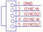
To synchronize DAP boards, a cable needs to connect the J13 connector on each DAP. The synchronization connector allows several DAP boards to share the same sampling clock and output update clock. The J13 connector has a single row of five pins on 0.100-inch centers. It is located along the top edge of the DAP board near the right side of the board. The pinout is shown below. Pin 1 is closest to the gold finger of the board
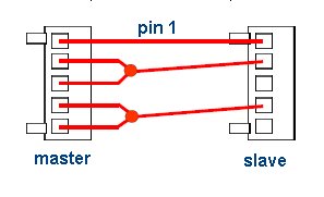
The clock outputs of the master board should be connected to the clock inputs of the slave board(s). Shown below are the connections between a master and a slave.
The part numbers for the five-pin female connector and the crimp pins are Molex 22-01-3057 and Molex 08-50-0114, respectively. A "master" connector requires one connector and five pins; a "slave" connector needs one connector and three pins. The wires used should be 22 AWG.
A synchronization cable can have multiple "slave" connectors for connecting more than one slave to a master DAP board. The distance between connectors should be minimal. The standard cable MSCBL101 from Microstar has the connectors at 3.2" apart.
L