Capturing serial data
Capture Serial Data Without Extra Hardware
(View more Software Techniques or download the command module.)
This article describes a method, that certain applications can use to advantage, for capturing information arriving on a serial communication link (RS-232, RS-422, RS-485, EIA 232, TIA 232, etc.) and for coordinating this with other measurement activity on a Data Acquisition Processor board.
For some applications, all of the information arrives in the form of raw voltage and current signals, and a DAP board is what you need. For other applications, the information arrives in an encoded, serialized form, and in general you need a communication interface board, not data acquisition hardware. The tricky cases are the ones with a mix of information sources, some in the form of raw signals and others serialized. Juggling two sets of hardware is awkward at best. It would be helpful to capture the data all in one place.
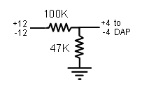
Sometimes this is possible, using a spare input pin on a Data Acquisition Processor board. Here is the basic idea. Serial data are typically produced at conventional digital TTL logic levels, and delivered at higher level analog levels. For example, a PC-compatible serial port uses -12 to +12 volt signal levels. A TTL-level signal can be attached directly to a pin on a DAP digital input port. Or a high-level analog signal can be attached to a spare analog input pin. Voltages beyond the normal -5 to +5 range can use a protective "voltage divider" circuit on the termination board, as illustrated below.
Few applications completely use all available input signal pins. That means that in most cases, a spare pin is available and can be used "essentially for free." You don't have to buy additional communications boards or communications software, install extra drivers, or cope with additional timing problems in your PC host system.
How this works
There is one practical difficulty with this idea. The conventional (we could say normal) way to capture this signal is by using a serial communications chip. The chip will detect incoming logic edges that flag the arrival of a data packet, and from this activate an internal timer for locating each bit in the time-multiplexed digital sequence that follows. A DAP board does not have this hardware logic. But what it does have is the sampling, timing, and processing power of the onboard DAP processor. Instead of edge triggering in hardware, the DAP samples the digital logic signal just as it would any raw signal. It must do this often enough to guarantee that every bit is observed, and latch the data bits at exactly the right times.
This is where the RSXDECODE processing command can help. To reliably sample the serial data stream, you should try to sample at 3 times the baud rate or higher. (Much higher rates are inefficient, but not otherwise harmful.) Tell the RSXDECODE command the baud rate of the serial encoding, and the capture rate of the sampling. It will then apply an optimal strategy for converting the observed bit stream into the equivalent data packet. The RSXDECODE command also accepts all of the usual configuration options for data bits, stop bits, parity and so forth, so you can easily configure it to match your signal transmitter equipment. The output is a stream of message packets, typically "text characters."
Your problems are not completely solved. Messages arrive through the serial port at a slow rate, with delays to format the messages and to transfer them. But this is the nature of the beast. You will face these same difficulties no matter how you record serial data.
An example application
Consider a suspension test of a vehicle moving around a large test track. The vehicle might be observed using several instruments, some in the vehicle and some ground-based. When the data are analyzed, time and position are determined from messages received from a GPS receiver. The GPS receiver delivers its information as straightforward NMEA 0183 Standard text message packets, such as type RMC sentence containing position, speed, and time-of-day information. These packets are transferred via an RS-232 serial connection.
This leads to a two-step problem, with a two-step solution. The first step is to apply the RSXDECODE command to recover the text of the GPS messages. So far so good, but the information remains in a hard-to-use text form. The second step is to apply the GPSRMC processing command to extract the information fields that you want from the messages. The result is a consistent binary form that is efficient for transfer to your PC host machine and easy to analyze.
Here is the DAPL configuration representative of the one you might use for this application. First, the sampling configuration. Suppose there are four data channels to be captured 5000 times per second each. The GPS messages arrive on a fifth analog signal line. The sampling configuration looks something like this:
  IDEFINE  mixedsamples
    CHANNELS  10
    SET   IP0   S4      // Serial
    SET   IP1   S0      // Analog 1
    SET   IP2   S4      // Serial
    SET   IP3   S1      // Analog 2
    SET   IP4   S4      // Serial
    SET   IP5   S2      // Analog 3
    SET   IP6   S4      // Serial
    SET   IP7   S3      // Analog 4
    SET   IP8   S4      // Serial
    SET   IP9   G       // Nothing sampled
    TIME  20.0
  END
Each sweep through the list of 10 channels takes 200 microseconds, 20 microsecond intervals between samples. Since each of the analog channels is captured once per sweep, they are sampled at the desired 5000 samples per second rate. The serial communications line is sampled 5 times at equal time intervals during the same time period, which means 25000 observations of the digital signal per second. The GPS messages are typically delivered at 4800 baud, consistent with requirements of the NMEA 0183 Standard. The 25000 samples per second is larger than the recommended 3x4800 samples per second, but no harm done by the extra samples, and the reliability of capture will be very good.
Now onboard processing can be configured to recognize the serial data. After passing through the protective voltage divider, the serial signal voltages range from -4 volts to +4 volts (out of a full range of -5 to +5 volts), active low. There are 8 data bits with no parity bit and one stop bit. The baud rate 4800 and sampling rate 25000 are specified. Results from rigidly clocked analog signal measurements (pipe $Cp2Out) and asynchronous GPS messages (pipe $Cp3Out) are delivered to the host system through separate channels.
  PDEFINE  collect
    // Separate analog and serial data channels
    serialdat = Ipipe(0,2,4,6,8)
    analogdat = Ipipe(1,3,5,7)
    // Decode serial messages
    RSXDECODE(serialdat, -26206,26206, -1,  \
       8, -1, 1,  255, \
       4800, 25000,  messages)
    GPSRMC(messages, "TIME,LATDEG,LONGDEG", $Cp3Out)
    // Transfer the measurement data
    COPY(analogdat, $Cp2Out)
  END
Availability
The usual policy on license and deployment fees applies. That is...
Don't put up with it.
Why pay us to use your own applications? Download the commands and try them with your DAP board, no charge. If they work for you, use them, no charge.
Conclusions
Sometimes the advantages of Data Acquisition Processor boards show up in the most unlikely places... like processing a serial data signal without a serial data port. That's just one of the things a reserve of processing power can do. You just need to take advantage when the time is right. Judicious application of the RSXDECODE command allows you to monitor serial data routed to a spare input pin, avoiding extra communications hardware and software. The additional processing you need? Not a problem, just download the SERIALM processing module and give it a try.
Return to the Software Techniques page or download the SERIALM command module. The download contains detailed information about the RSXDECODE and GPSRMC commands described in this page.